For this project we had to display our date of birth on one seven segment display. Whenever I switch a switch on my board the number changes each time and all together they make my date of birth. We had to use a kathode display, and I used karnaugh mapping to simplify the expressions. We also had to make one curcuit using NAND or NOR.
TRUTH TABLE
Truth table is to show what combination of X Y or Z makes a certain letter on the display and it also shows what each circuit's expression must be.

There is an A-G column because A-G is each segment in the 7 segment hex display. With all 7 letters on it will make an 8, and you combine different letters to make it display different numbers or symbols.
Karnaugh Maps and Simplified Logic EXPRESSIONS
To make the k-maps you use each column of the truth table and plug the numbers in order, but the last 2 are switched with the second to last 2 numbers. Then you group the 1s and Xs into the biggest groups possible and write what the expressions are for each table. K-Mapping is a lot easier then Boolean algebra, there is less opportunities for mistakes, and it is also a lot faster. There is an expression for each letter for the seven segment displays, so there are seven logic expressions.
mULTISIM CIRCUIT

This circuit is in bus form. It uses 6 74LS00, 2 74LS02, 2 74LS32, 1 74LS08, and one 74LS04. I used 6 chips to make this circuit. I didn't choose to use NAND for any specific circuit to make it easier or simpler, I just used the first expression and converted it toNAND. We use NAND or NOR gates because sometimes you will use less ICs which will make the circuit cheaper. A seven segment display has 7 different segments in it, which are named A-G. The picture below shows what segments are where. You use different segments that light up to produce different numbers, letters, or symbols. A common cathode display is grouned, so to make a segment light up you want to produce a 1. A common anode display is powered so to make a segment light up you want a 0. I used a common cathode display because we were told to use it and it makes more sense that a 1 lights it up and not a 0. The resistor is there so the seven segment display doesn't get overpowered and get ruined.

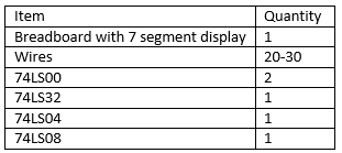
Date of Birth Circuit Bill of Materials
This table shows all the items needed to breadboard the project.
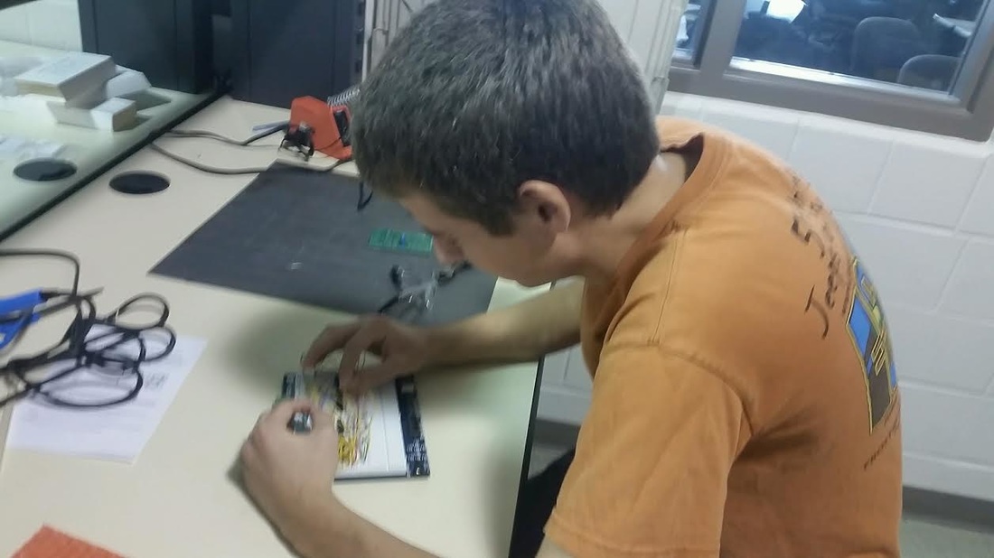
BREADBOARING
The last time I bread boarded I tried to do it fast so I would have more time to make the weebly but it ended up causing me to waste more time on trying to figure out what was wrong then actually making it. This time I went slower and it did not work the first try, so I found out that letters F and D were not functioning correctly so I traced back both segments and they were perfectly fine. I double checked using the papers that show where the inputs and outputs are on the ICs and they were all good. I couldn't figure out what was wrong with it and it ended up just being a wrong IC because I didn't double check that it was the right one when I took it out of the drawer.
CONCLUSION
I learned a lot about 7 segment displays and how they work, like that they have different segments that each have a separate circuit. If I did this again I would breadboard slower and make sure everything is correct while building because troubleshooting takes up a lot of time. Using K-Mapping is faster for me. I also am more consistent with getting the correct simplified expression when I use it instead of boolean algebra.
