Ryan Sauer Digital Electronics 1/14/15
State graph
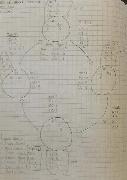
The inputs are two limit switches and two switches for manual input. The inputs depend on the current state while the outputs depend by the next state. The sate it is in is dependent on what sensors are open or closed and if a switch is on or off.
So if a toll gate is closed, switch opens it which makes motor run until it hits the open limit sensor. Then to be closed the other switch is hit to make the motor turn on and close the gate until it hits the closed limit sensor.
So if a toll gate is closed, switch opens it which makes motor run until it hits the open limit sensor. Then to be closed the other switch is hit to make the motor turn on and close the gate until it hits the closed limit sensor.
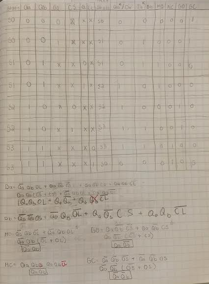
transition table
conclusion
Dear Mrs Z,
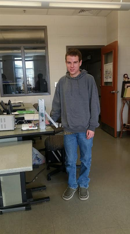
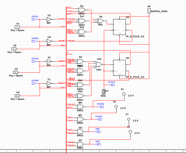
The first thing we had to do is make a state graph. Then we took the state graph and put that info into a transition table. We then used that transition table to get the 6 expressions we needed. Then using boolean algebra we simplified the 6 expressions. We made some mistakes with the boolean algebra, but they were very simple mistakes that were made just because we were rushing to get it done so we could start the multisim. We then used those expressions and Imani put them onto multisim while I built the actual tool booth and wired the breadboard. After the multisim was completed it wasnt functioning properly and that is when we checked over it all on the computer first, then checked the boolean algebra and found the mistakes. After transferring the PLD onto the programmable chip it was functioning properly. Major physical components to this design were the limit switches to sense when the tool booth gate was open or closed and the switches to make the motor run to open or close the gate. This project was different because it was our first State Machine project. A state machine is a circuit that makes devices go through states in particular order. This project was definitely easier then in the beginning of the year because I have gotten a lot of experience from other projects and classwork/hw we have done like boolean algebra, working with multisim, and wiring. That all makes it easier to design and even troubleshoot this project.
The first thing we had to do is make a state graph. Then we took the state graph and put that info into a transition table. We then used that transition table to get the 6 expressions we needed. Then using boolean algebra we simplified the 6 expressions. We made some mistakes with the boolean algebra, but they were very simple mistakes that were made just because we were rushing to get it done so we could start the multisim. We then used those expressions and Imani put them onto multisim while I built the actual tool booth and wired the breadboard. After the multisim was completed it wasnt functioning properly and that is when we checked over it all on the computer first, then checked the boolean algebra and found the mistakes. After transferring the PLD onto the programmable chip it was functioning properly. Major physical components to this design were the limit switches to sense when the tool booth gate was open or closed and the switches to make the motor run to open or close the gate. This project was different because it was our first State Machine project. A state machine is a circuit that makes devices go through states in particular order. This project was definitely easier then in the beginning of the year because I have gotten a lot of experience from other projects and classwork/hw we have done like boolean algebra, working with multisim, and wiring. That all makes it easier to design and even troubleshoot this project.
