Ryan Sauer 10/18/2015 Digital Electronics
The purpose of this project was to make a circuit that resembles how a decision is accepted or denied. The decision is voted on by four people. To be accepted the president and at least one other person must vote, or 3 non president votes.
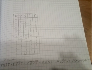
The truth table shows when the output is a 1 and when it is 0. It shows what value is needed to make the expression a 1 or 0. If there is a tie the decision is not passed. 2^x is how many rows there are. X being the number of variables.
The expression is in sum of products form. The minterms are when the output is one.
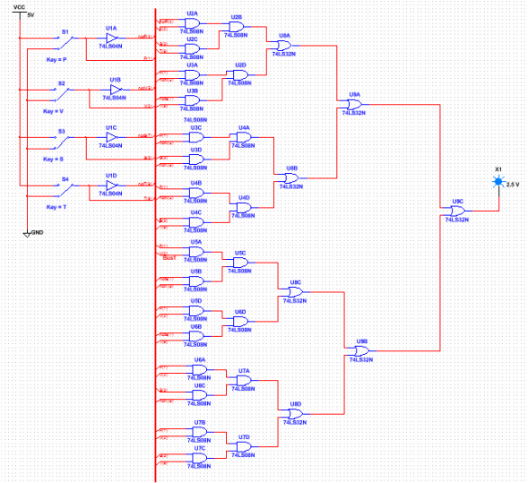
The circuit is in bus form, which makes it look a lot nicer. 35 gates are required, which are not all needed after it is simplified. 11 chips are needed to make this circuit on a breadboard.
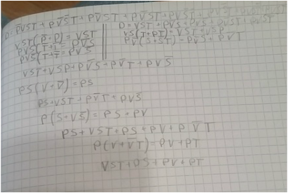
Boolean algebra is used to simplify a circuit. Shown below is a photo of how to simplify the expression for the circuit above.
Boolean algebra is used to simplify a circuit. Shown below is a photo of how to simplify the expression for the circuit above.
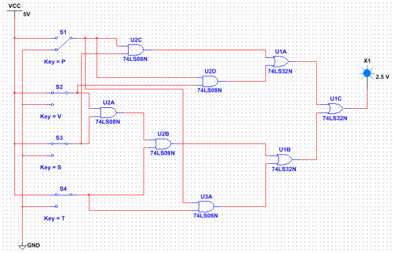
The above circuit could be in bus form to make it look better, but it is not. The resistor makes sure there isnt too much power going to the led which could blow the bulb. Only eight gates are needed to make this circuit. It contains 28 less gates then the unsimplified circuit.
The simplified circuit is a lot cheaper to make. This is because you do not need as many gates. It is also a lot easier to make since there is not as many components in the circuit.
The simplified circuit is a lot cheaper to make. This is because you do not need as many gates. It is also a lot easier to make since there is not as many components in the circuit.
Majority vote circuit bill of materials

This table shows the materials needed to make the simplified circuit.
These pictures show my completed breadboard from different angles so you can see how it is all set up. To make it i followed the simplified expression and made each minterm then added them together. Then put in the resistor and LED last. My circuit did not work at all so i first checked every wires position and compared it to other peoples circuits. After multiple tries it turned out that the LED was broken.
Conclusion
In this project I learned a lot about modeling a circuit on the computer, like that you can use a bus so it is not confusing to follow all the connections. I also learned to make the circuit slower next time because finding out what is wrong after making it fast takes more time then doing it the correct way the first time. Boolean algebra makes expressions easier to understand and easier to make into actual circuits.
