Project OVERVIEW
|
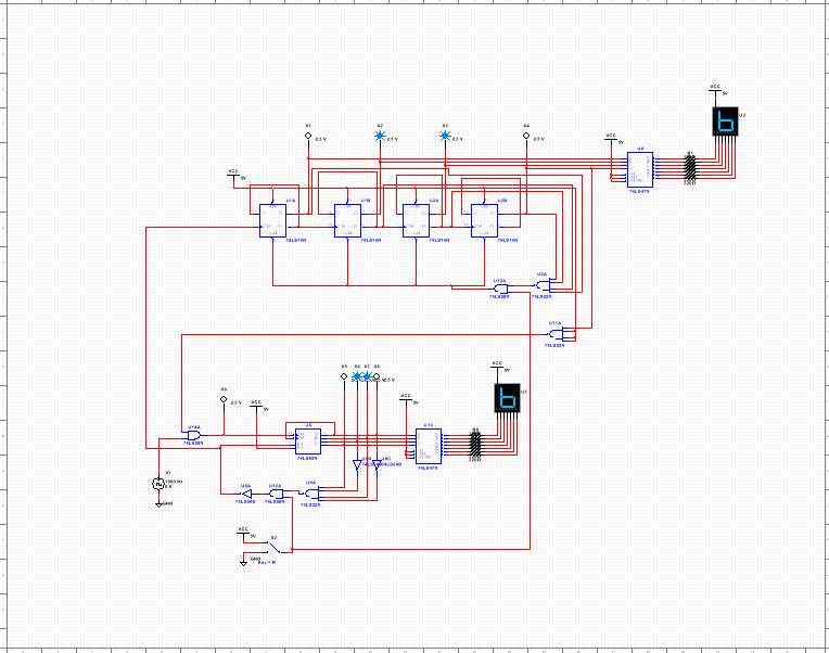
The DMV counters purpose is to count from 0-80 and suspend at 80, but once the reset switch is switched it goes back to 0, thenif it is switched back it counts starting at 0 again.
|

|
Multisim circuit
Design mode
PLD Mode

In PLD mode you have to have input and output connections so it can work when you make it on a board. Input connectors are for clocks, while outputs are for probes, boards, ect. So PLD mode is mainly so you can upload the circuit to a board, while in design you can see if it works and connect it to displays. All you do to program chip is plug it in with usb cable and then transfer it onto the chip.
Bill of MATERIALS

This table shows what materials were used while bread boarding
Conclusion
SSI means Small Scale Integration, while MSI means Medium Scale Integration. The limitations of the MSI circuit is that it always has a lower limit of 0 and it cant be a down counter. SSI circuits can have a lower limit and can also be a down counter. SSI uses multiple flip flops. The ripple effect is when there is a delay in the circuit, just like how ripples in water have different spacing. The SSI circuit was used to control the 10s place which counted from 0-8, while the MSI was used for the ones that counted 0-9. When you turn the switch on the circuits work together to count up to 80. The MSI had to count 0-9 every time the SSI number changed. I can reset the circuit anytime back to 0 by switching the switch off. Once it gets to 80 it is suspended and to get it to count again you have to reset it back to 0 using the switch and switch it back on. My project was similar to everyone elses except when it was bread boarded because you could assign different thing to pins, except pin 14 that had to be the clock.
